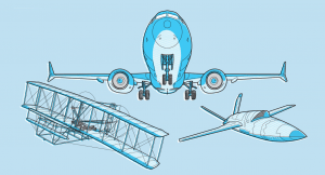

Defining the various loads applied to aircraft structures, in regards to the design and construction of the fuselage, wing and tail section. Materials used in construction and the effects of corrosion and fatigue will be considered. Effects of a hard landing on the airframe, failure statistics are important in safe aircraft design.
Loads are applied to the aircraft structures both on the ground and in flight, and methods are employed to mitigate the effects of corrosion and fatigue.
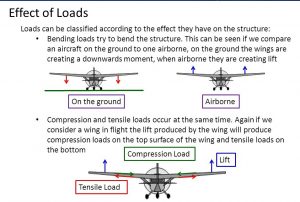
Tension
A tensile load is one which tends to stretch a structural member. The member is then said to be under tension. Components designed to resist tensile loads are known as ties. For example, stringers which in modern aircraft take the tensile loads produced in the fuselage structure by pressurization.
Compression
Compressive loads are the opposite of tensile loads and tend to shorten the structural member. Members under compressive loads are said to be under compression. Components designed to resist compressive loads are known as struts.
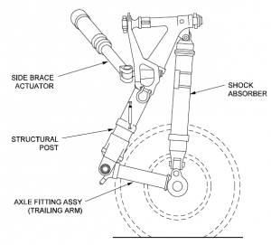
For example, landing gear contains numerous struts, the primary one being the oleo pneumatic strut which takes compressive loads on landing.
Shear
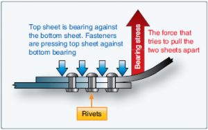
Shear is a force which tends to slide one face of a material over an adjacent face. Riveted joints are designed to resist shear forces. Rivets are used to fasten the fuselage skin. In modern aircraft they are being replaced by adhesive bonding processes.
Most loads to which aircraft components are subjected to are a combination of two or all three of these basic loads.
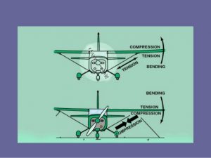
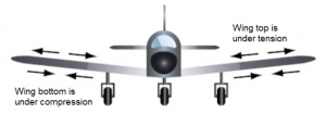
Bending
Bending involves the three basic loads.
Tension on the outer edges, compression on the inner edges, shear across the structure as forces try to split it.
Torsion or twisting force produce tension on the outer edge, compression in the center, and shear across the structure.
Buckling
Buckling occurs between two thin sheets of materials when they are subject to end loads and between two ties when subject to compressive forces.
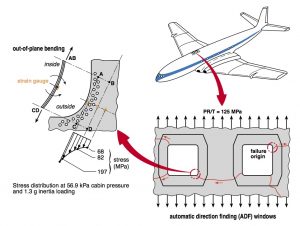
Stress
Stress is the internal force inside a structural member which resists an externally applied force. A tensile load or force will setup a tensile stress. A compressive load will apply a compressive stress. Stress is defined as the force per unit area and is measure in N/mm2 or mN/m2
When an external force of sufficient magnitude acts on a structure, the structural dimensions change. This change is known as strain.
Strain = Change of length / Original length
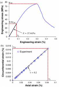
Strain is a measure of deformation of any loaded structure. The 18th Century English Physicist Thomas Young discovered the relationship between stress and strain for an elastic material within its elastic limit is generally a constant. The constant is therefore known as
Young’s Modulus of Elasticity
STRESS / STRAIN = Young’s Modulus
Aircraft components are subjected to some or all of these stresses and they will tend to elongate, compress, bend, shear and twist the component.
However, provided the deformation is within the elastic limit of the material the component will return to its original dimension once the stress has been removed.
If any load takes the structure beyond its elastic limit then the deformation will be permanent.
The maximum load that a designer would expect an airframe or component to experience in service is termed as the design limit load.
The load is defined as a load factor, G = Lift / Weight
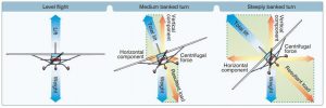
The load factor is expressed in terms of multiples of G
In straight and level flight, Lift = Weight
Load Factor = Lift / Weight = 1G
Aircraft are designed with different limit loads depending on their type of service.
Public Transport – 2.5G
Utility Aircraft – 3.4G – 3.8G
Aerobatic Aircraft – 6G
Design Ultimate Load is defined as the design limit load multiplied by the safety factor.
Design Ultimate Load (DUL)=Design Limit Load x Safety Factor.
The minimum safety factor specified in design requirements is 1.5
The structure must withstand its design ultimate load without collapse
Safety Factor = Design Ultimate Load / Design Limit Load = 1.5
The aircraft manufacturers will attempt to design an aircraft to take into account all the loads it may experience in flight or when landing.
There are various guidelines, formula and experience to help them in the design of good, fail-safe and damage tolerant structures. The designer will take into account the anticipated role of the aircraft. So, for instance, an aircraft designed for long-haul operations should not be used for short-haul as the extra take-offs and landing will not have been accounted for in the airframes anticipated fatigue life calculations.